
ECEN-4350
Embedded Microcontroller Design
Wi-Fi Synthesizer Project
Daniel Faronbi
Fall 2019
Department of Electrical
&
Computer Engineering
University of Nebraska-Lincoln
(Omaha Campus)

Daniel Faronbi
Summary
2
Table of Contents
1 SUMMARY
3
2 OBJECTIVE
3
3 PROCEDURE OR TEST PLAN
3
4 HARDWARE DISCUSSION
4
5 SOFTWARE DISCUSSION
5
6 PROBLEM DISCUSSION
8
7 CONCLUSION
8
8 APPENDIX
8

Daniel Faronbi
Summary
3
1
Summary
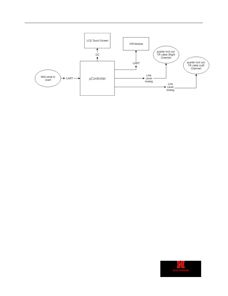
The Wi-Fi Synthesizer project was conceptualized as a device to read midi input and generate audio
waveforms based on the information provided by the midi signal. The device would also transfer the
midi signal received via Wi-Fi to a website by a http request. The midi component of the project was
not included in the final application because of time restraints, but the circuitry was still included in
the design. The final application outputs a 100hz audio signal with a user selected wave shape (selected
from four options). The device will send data to a website indicating which waveform was last selected.
2
Objective
The objective of this project was to give students experience designing a modern embedded
microcontroller system. The project was required to have a sensor and to transmit data via radio. My
project had touch input as a sensor and transmitted data via Wi-Fi. It also interfaces with an LCD
display and outputs audio from a ¼ TR cable. The project was also required to communicate with
other modules using a variety of serial protocols. In my project, I used SPI to communicate with the
LCD, I²C to communicate with the touch screen, and UART to communicate with the ESP8266 Wi-
Fi module.
3
Procedure
The design of this project was split into three different categories, conceptualization, component
picking, breadboarding, and final board design.
Conceptualization
In the conceptualization phase, I organized what modules were needed for the design and created a
block diagram as seen in Figure 1. This provided a template that could be elaborated on to create a
more robust realization of the project.
Component Picking
Once the block diagram was created, I decided on the specific modules I would need to build my
device. For the microcontroller I selected the NXP LPC 4088. For the touchscreen LCD display, I
used the Adafruit TFT Touch Shield, for the Wi-fi module, I used the ESP8266-12E.
Breadboarding
For the breadboarding phase, I tested interfacing with the different modules using a dev board for my
modules on the development board, I documented the changes to the interfacing of the dev board in
Eagle Cad, so that the correct schematic would be available when the PCB would need to be
generated.

Daniel Faronbi
Hardware Discussion
4
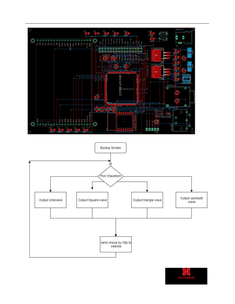
Final Board Design
For the final board design, I made a schematic for the board in eagle, as well as a PCB layout. These
are available in Figures 2 - 6. Voltage regulators, capacitors, resistors, LEDs, MIDI port, TR ¼ inch
audio port, opto-isolator, power jack, 10 pin JTAG programming header, and pin headers were added
to the design to flesh out the functionality. Many components were surface mounted, allowing for
components to be placed on the front and back of the board. Once I was done with the board layout, I
application.
4
Hardware Discussion
The hardware design was split into a variety of components. These include the MCU
configuration, LCD display, power Circuitry, audio output circuitry, Wi-Fi module circuitry,
MIDI circuitry, JTAG circuitry, I²C circuitry, reset circuitry, coupling capacitors, and pin
headers.
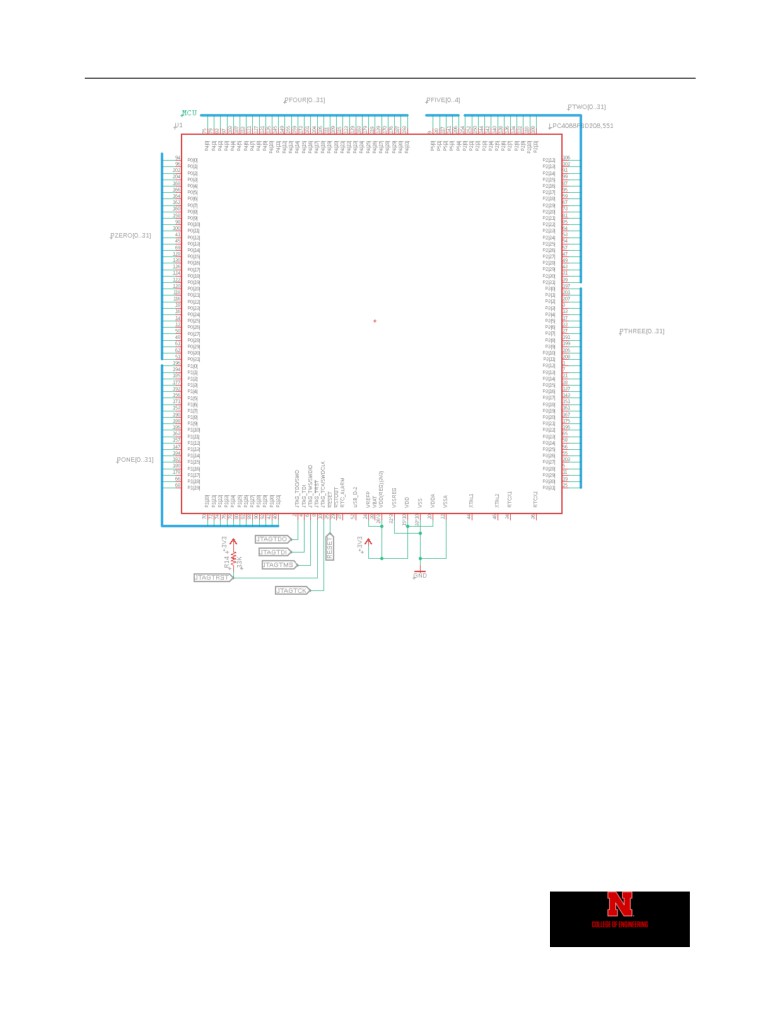
MCU
The connections to the MCU can be seen in Figure 5. The MCU used for this project was the
LPC4088FBD208. This is an ARM Cortex-M4 based microcontroller with peripherals for SPI,
I²C, DAC, DMA and many more. The final design included a quad package version of this
controller. The MCU was connected to multiple power lines (3.3volt powering), reset
circuitry, JTAG circuitry, connections to modules, and power for the analog in and out
functions of the microcontroller.
LCD Display
The connections to the LCD display can be seen in Figure 4. The LCD used for this project
was the 2.8” TFT Capacitive Touch Shield. The LCD was connected to a 5 volt power supply,
The SPI1 peripheral of the MCU (these includes MOSI, MISO, CLK, and CS from port 0 pins
9, 8, 7, and 6 respectively), touch screen controls ( I²C0 SDA and SCL from port 5 pins 2 and
3 respectively), and an interrupt generator on port 0 pin 24.
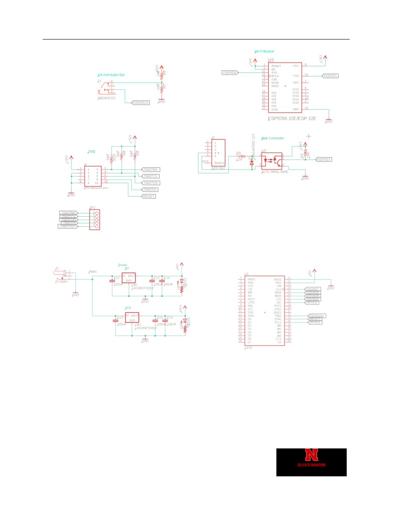
Power Circuitry
The connections to power circuitry can be seen in Figure 4. It consists of a power jack, two
voltage regulators, six stabilizing capacitors, 2 LED lights, and 2 resistors. The power jack
used was the PJ-048H. The voltage regulator I used were 3.3- and 5-volt versions of the
LM1086TO263.
Audio Output Circuitry
The connections of the audio output circuitry can be seen in Figure 3. It consists of two
resistors and a ¼ inch TR headphone jack output. The NMJ4HCD2 was used for the ¼ TR
jack. Two 100-ohm resistors were in series to provide a digital ground, so that negative
voltages could be possible.

Daniel Faronbi
Software Discussion
5
Wi-Fi Module
The connections of the Wi-Fi module can be seen in Figure 3. The Wi-Fi module used for
this project was the ESP8266-12E. it was powered by 3.3 volts, connected to UART3 (port 0
pins 0 and 1), and reset and enable pins were tied to VCC (3.3 volts).
MIDI Circuitry
The connections of the MIDI circuitry can be seen in Figure 3. It consists of a 5 pin MIDI
connector, an optocoupler, a diode, and resistors. The SDS-50J was used as the 5-pin MIDI
connector. The ACPL-M50L-000E was used for the optocoupler.
JTAG Circuitry
The connections of the JTAG circuitry can be seen in Figure 3. It provides a 10-pin
connector for programming the devices and headers to debug JTAG signals. Pullup resistors
were provided on the TMS, TCK, and TDO for SWD connection.
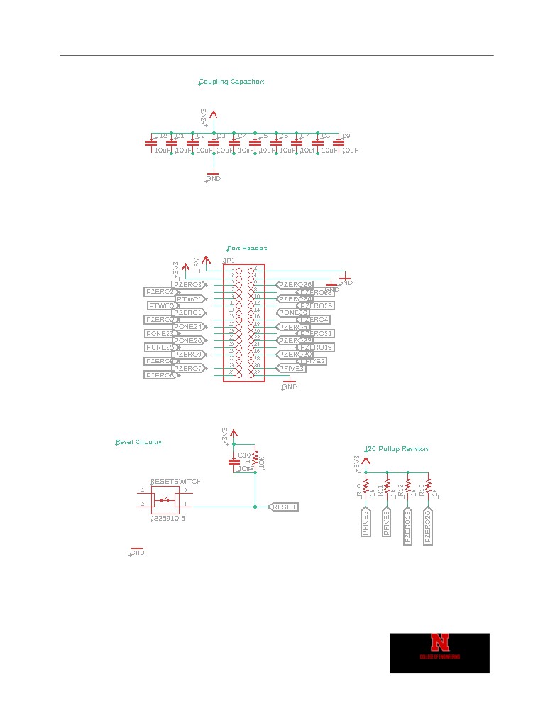
I²C Circuitry
The connections of the I²C circuitry can be seen in Figure 2. It provides pullup resistors on
port 5 pins 2 and 3 and port 0 pins 19 and 20.
Reset Circuitry
The connections of the reset circuitry can be seen in Figure 2. It consists of a reset switch, a
stabilizing capacitor, and a pullup resistor.
Coupling Capacitors
The connections of the coupling capacitors can be seen in Figure 2. These were a series of
capacitors connected from 3.3 volts to ground to help stabilize the voltage of the board.
Pin Headers
The connections of the pin headers can be seen in Figure 2. These were used to provide
easy access to important MCU pins.
5
Software Discussion
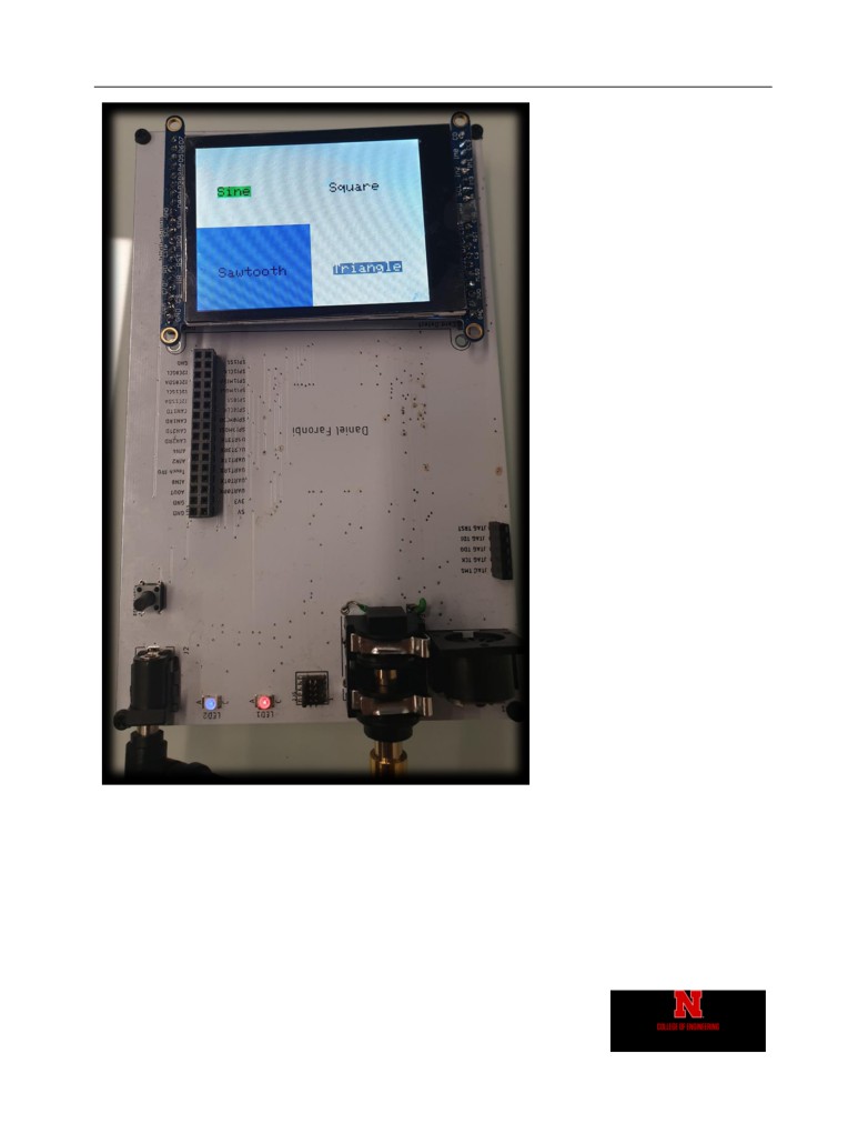
The device was designed to send out audio waveforms and data over Wi-Fi. The application
boots up, then allows the user to select a waveform by touchscreen. The selected
waveform is outputted from the audio port and sent over Wi-Fi to a google server, so that
it can be displayed on a website. Figure 7 shows a flowchart for the application. Figure 8
shows the website where the received data is displayed.

Daniel Faronbi
Software Discussion
6
probe. The software was written in C and the ARM GDB compiler was used to generate the
machine code. The code was split into a variety of files to make it more readable. These
files included wifisynth.h, wifisynth.c, adc.c, dac.c, dma.c, ESP8266.c, gpio.c, i2c.c, lcd.c,
osc.c, ssp.c, sysTick.c, timer.c, and uart.c. The website also had code written in Google Apps
Script.
wifisynth.h
This file contains defines and function prototypes that are used throughout the software.
Every other file includes the “wifisynth.h” file. This file also includes useful libraries. The
“chip.h” library provides functions for modifying LPC 4088 registers and the “math.h”
function provides useful math functions.
wifisynth.c
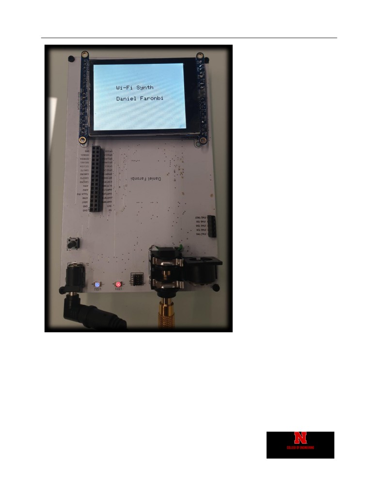
This file contains the main code used to run the application. First, the software initializes
all the MCU peripherals. Next, it writes a splash screen. It then displays option waveforms
for the user to pick and waits for the user to touch the screen. Depending on where the
user touches the screen, the waveform output will be changed, and data will be sent to the
website over Wi-Fi.
adc.c
This file contains the code used to configure the LPC 4088’s analog to digital converter
peripheral. This peripheral was not used in the final application but was used during the
breadboarding stage. The file includes functions to initialize the ADC and read data from
the peripheral.
dac.c
This file contains the code used to configure the LPC 4088’s digital to analog converter
peripheral. It contains functions to initialize the DAC and write a value to the DAC. The
output from the DAC was the audio signal generated by the software.
dma.c
This file contains the code used to configure the LPC 4088’s direct memory access
peripheral. It contains functions to initialize the DMA and send more data at an interrupt
request. This was originally supposed to be used in conjunction with the DAC to output a
steady stream of audio with a buffer, but timer 1 was used instead in the final application.

Daniel Faronbi
Software Discussion
7
ESP8266.c
This file contains the code used to interface with the ESP8266 Wi-Fi module via UART. It
contains functions to send a string to the ESP8266, reset the device, setup the devices Wi-
Fi mode, access point, and IP mode, send data to website, and connect to website. The LPC
4088 UART3 peripheral was used to interface with the Wi-Fi module.
gpio.c
This file contains the code used to configure the LPC 4088’s general purpose input and
output peripheral. It contains functions to initialize GPIO ports and generate an interrupt
on the falling edge of port 0 pin 24. Unfortunately, the interrupt feature caused a hardware
fault, so it was not used in the final design.
i2c.c
This file contains the code used to configure the LPC 4088’s inter-integrated circuit
peripheral. It contains functions to initialize the I²C peripheral, write I²C data, and read I²C
data. It also contained functions to write and read I²C commands. The I²C0 peripheral of
the LPC 4088 was connected to the touch screen.
lcd.c
This file contains the code used to interface with the LCD display module trough SPI. It
contains functions to initialize the display and write a variety of shapes and text to the
screen. This was used to display all the menus of the application.
ssp.c
This file contains the code used to configure the LPC 4088’s serial peripheral interface. It
contains functions to initialize the SPI peripheral, flush data, write data, and read data. The
LPC 4088’s SSP1 peripheral was used to interface with the LCD display.
sysTick.c
This file contains the code used to configure the LPC 4088’s system timer peripheral. It
contains functions to initialize the system timer, update a counter every millisecond, and
generate microsecond or millisecond delays. This timer was used to keep track of time
when generating waveform data and generate delays when needed.
timer.c
This file contains the code used to configure the LPC 4088’s timer peripheral. It contains
functions to initialize the timer peripheral, start the timer, and clear the timer when the
value is matched. The timer0 peripheral was used to generate delays for the ESP8266
module. The timer1 peripheral was used to periodically send waveform data out of the
DAC.

Daniel Faronbi
Problem Discussion
8
uart.c
This file contains the code used to configure the LPC 4088’s universal asynchronous
receiver transmitter peripheral. It contains functions to initialize the UART, send string and
character data, and receive data via interrupts. UART0 was supposed to be used for MIDI
input, but this was not included in the final application. UART3 was used to interface with
the ESP8266 Wi-Fi- Module.
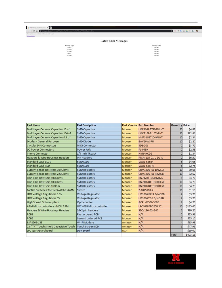
Website
The website Google apps script and html work together to display the latest waveform.
They store this data in a google spreadsheet. The html reads the google sheet to display
the contents of the latest waveforms.
6
Problem Discussion
While trying to complete this project I had two big issues. The first issue was programming
the final microcontroller. The second issue was generating interrupts from touch input.
Programming Issue
After ordering my first board and soldering on the parts. I attempted to program it. The
device programmed the first time, but it was not recognized after being programmed once.
I tried swapping out different microcontrollers and circuit boards and changing the JTAG
and SWD connections and pullup resistors. None of these worked. Finally, I ordered a new
circuit board. I still had the same problem. Eventually I realized that I needed to program
my board with MCUXpresso IDE instead of the older LPCXpresso IDE I was using. The
debugging and programming worked perfectly after this switch.
Interrupt Issue
When trying to generate an interrupt from the touch screen, the device always generated a
hardware fault. The GPIO interrupt did not work. I never figured out a solution to this
problem, so I instead used polling to check for touch input.
7
Conclusion
After completing this project, I feel very confident designing my own embedded system. The process
of picking a microcontroller and module seemed daunting at first, but now I understand the process
well. I also feel confident doing surface mount soldering. I used both a soldering oven and heat gun
for the first time when building this project. I am glad that I have learned these skills and I know they
Daniel Faronbi
Appendix
9
8 Appendix
Figure 1 - Initial Block Diagram of Design
Daniel Faronbi
Appendix
10
Figure 2 - Schematic Part 1
Daniel Faronbi
Appendix
11
Figure 3 - Schematic Part 2
Figure 4 -Schematic Part 3
Daniel Faronbi
Appendix
12
Figure 5 - Schematic Part 4
Daniel Faronbi
Appendix
13
Figure 6 - Board Layout
Figure 7 - Flow Chart
Daniel Faronbi
Appendix
14
Figure 8 - Website
Figure 9 - Bill of Materials
Daniel Faronbi
Appendix
15
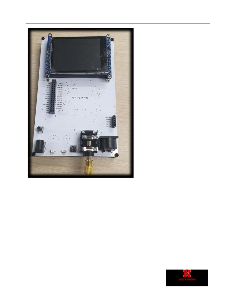
Figure 10 - Device Front
Daniel Faronbi
Appendix
16
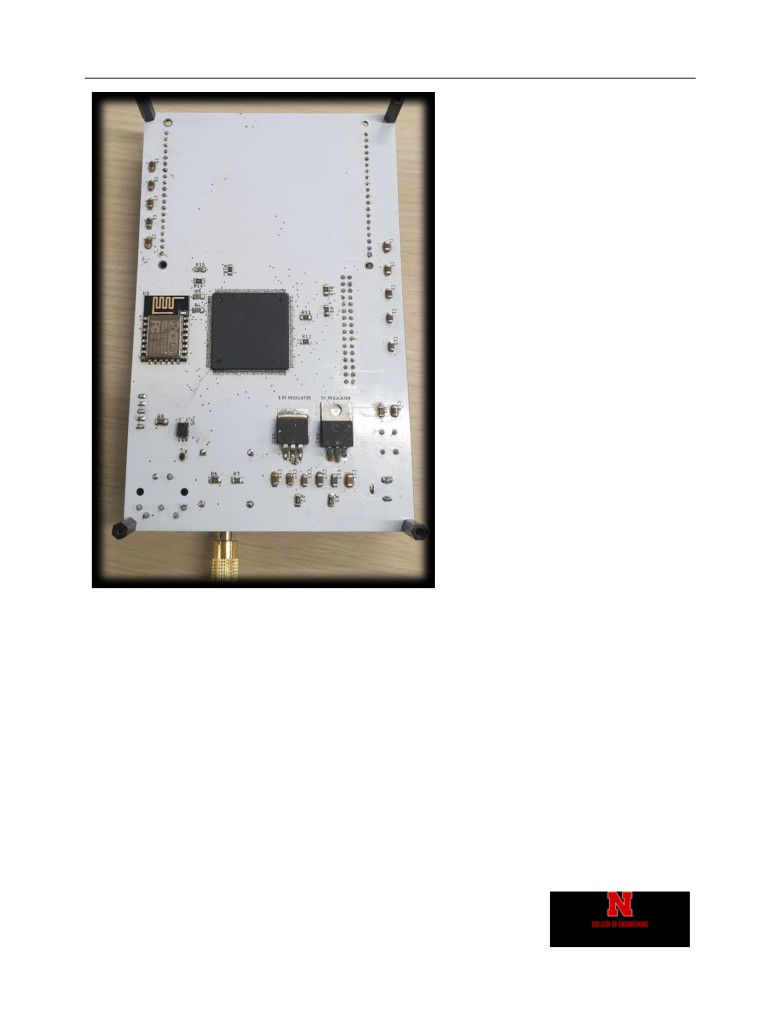
Figure 11 - Device Back
Daniel Faronbi
Appendix
17
Figure 12 - Splash Screen
Daniel Faronbi
Appendix
18
Figure 13 - Select Screen

Daniel Faronbi
Appendix
19
Figure 14 - 100 Hz Sine Wave Generated
Figure 15 - 100 Hz Square Wave Generated

Daniel Faronbi
Appendix
20
Figure 16 - 100 Hz Sawtooth Wave Generated
Figure 17 - 100 Hz Triangle Wave Generated
Daniel Faronbi
Appendix
21
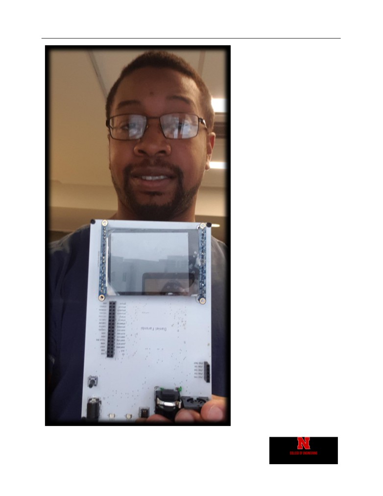
Figure 18 - Me and My project

Daniel Faronbi
Appendix
22

Daniel Faronbi
Appendix
23
Code
wifisynth.h
/*
* wifisynth.h
*
* Created on: Oct 19, 2019
* Author: danielfaronbi
*/
#ifndef WIFISYNTH_H_
#define WIFISYNTH_H_
//include defines for chip registers
#include "chip.h"
//include extra math functions
#include "math.h"
//port macros
#define set(portPin)
Chip_GPIO_SetPinState(LPC_GPIO,portPin,true)
#define clear(portPin)
Chip_GPIO_SetPinState(LPC_GPIO,portPin,false)
#define toggle(portPin)
Chip_GPIO_SetPinToggle(LPC_GPIO, portPin);
#define read(portPin)
Chip_GPIO_GetPinState(LPC_GPIO,portPin)
#define asOutput(portPin)
Chip_GPIO_SetPinDIROutput(LPC_GPIO,portPin)
#define asInput(portPin)
Chip_GPIO_SetPinDIRInput(LPC_GPIO,portPin)
//port pin names
#define LED1 1,18
#define LED2 0,13
#define LED3 1,13
#define LED4 2,19
#define CD
5,0
#define ADC 0,23
#define TOUCH 0,24
//numbers
#define PI 3.14159265358979323846
//lcd colors
#define BLACK 0x0000
#define GRAY 0xD6BA
#define BLUE 0x001F
#define RED 0xF800
#define GREEN 0x07E0
#define CYAN 0x07FF
#define MAGENTA 0xF81F
#define YELLOW 0xFFE0
#define WHITE 0xFFFF

Daniel Faronbi
Appendix
24
//audio buffer
#define BUFFSIZE
128
//esp8266 receive states
#define ESP8266_START 0
#define ESP8266_O 1
#define ESP8266_OK 2
#define ESP8266_R 3
#define ESP8266_RE 4
#define ESP8266_REA 5
#define ESP8266_READ 6
#define ESP8266_READY 7
//at commands
#define AT_RESET "AT+RST\r\n"
#define AT_WIFIMODE
"AT+CWMODE=1\r\n"
#define AT_JOINAP "AT+CWJAP=\"WiFi Synth\",\"pleasework\"\r\n"
#define AT_MUXIP "AT+CIPMUX=0\r\n"
#define AT_CONNECTWEB "AT+CIPSTART=\"TCP\",\"api.pushingbox.com\",80\r\n"
#define AT_NUMBYTES
"AT+CIPSEND=105\r\n"
#define AT_POSTWEB
"GET
/pushingbox?devid=v1A8E3909B06B76D&mType=\"cc\"&mValue=\"0xc\" HTTP/1.1\r\nHost:
api.pushingbox.com\r\n\r\n "
//touch screen quadrants
#define TOUCH_QUAD1
1
#define TOUCH_QUAD2
2
#define TOUCH_QUAD3
3
#define TOUCH_QUAD4
4
//gpio functions
void gpio_init(void);
//ssp functions
void ssp_init(void);
void ssp_flush(void);
void ssp_write(uint16_t);
uint8_t reverse8(uint8_t);
uint16_t ssp_read(void);
//wifi synth functions
void mcu_init(void);
char* hex4toString(uint8_t);
char* hex8toString(uint8_t);
char* hex16toString(uint16_t);
char* hex32toString(uint32_t);
//lcd functions
void write8(uint16_t );
void write8DataInline(uint16_t);

Daniel Faronbi
Appendix
25
void write8RegInline(uint16_t);
void writeRegister8(uint8_t, uint8_t);
void writeRegister16(uint16_t, uint16_t);
void setCursor(uint16_t, uint16_t);
void setTextColor(uint16_t, uint16_t);
void setTextSize(uint8_t);
void setAddress(uint16_t,uint16_t,uint16_t,uint16_t);
void TFT_LCD_INIT(void);
void fillScreen(uint16_t);
void drawPixel(uint16_t,uint16_t,uint16_t);
void drawCircle(uint16_t, uint16_t, uint16_t, uint16_t);
void fillRect(uint16_t,uint16_t,uint16_t,uint16_t,uint16_t);
void drawChar(uint16_t, uint16_t, unsigned char,uint16_t, uint16_t, uint8_t);
void write(uint8_t);
void LCD_string_write(char *);
unsigned char nibbleToASCII(uint8_t);
void hex4print(uint8_t);
void hex8print(uint8_t);
void hex16print(uint16_t);
//adc functions
void adc_init(void);
uint8_t adc_read(void);
//dac funtions
void dac_init(void);
void dac_updateValue(uint32_t);
//dma functions
void dma_init(void);
void DMA_IRQHandler(void);
//system tick timer functions
void sysTick_init(void);
void delay_us(uint32_t);
void delay_ms(uint32_t);
//uart functions
void uart_init(void);
void uart3_send(uint8_t);
void uart3_sendString(char*);
void UART3_IRQHandler(void);
void uart0_send(uint8_t);
void uart0_sendString(char*);
void UART0_IRQHandler(void);
//i2c funtions
void i2c_init(void);
void I2C0_IRQHandler(void);
void i2c_write(uint8_t, uint8_t*, int);
void i2c_read(uint8_t, uint8_t *, int);

Daniel Faronbi
Appendix
26
void i2c_readCmd(uint8_t, uint8_t, uint8_t *, int);
//timer functions
void timer_init(void);
void timer0_start(void);
bool timer0_matched(void);
void timer1_start(void);
bool timer1_matched(void);
//esp8266 functions
uint8_t esp8266_send(char*);
uint8_t esp8266_reset(void);
void esp8266_setup(void);
void esp8266_webSend(char*,char*);
void esp8266_connectSite(void);
//oscillator functions
void osc_sine();
void osc_square();
void osc_sawtooth();
void osc_triangle();
#endif /* WIFISYNTH_H_ */

Daniel Faronbi
Appendix
27
WIFI-Synth.c
/*
===============================================================================
Name
: WIFI-Synth.c
Author
: Daniel Faronbi
Version
:
Copyright
:Daniel Faronbi
Description : Wifi synth project main code
===============================================================================
*/
#include "wifisynth.h"
//variable to change how buffer is refilled
extern void (*refill_buf)();
/**
* @brief initialize all the peripherals needed for the mcu
*/
void mcu_init(void){
//Read clock settings and update SystemCoreClock variable
SystemCoreClockUpdate();
//initialize system clock
sysTick_init();
//initialize GPIO
gpio_init();
//initialize SPI
ssp_init();
//initialize ADC
adc_init();
//initialize I2C
i2c_init();
//initialize DAC
dac_init();
//initialize DMA
//
dma_init();
//initialize LCD
TFT_LCD_INIT();
//initialize uart
uart_init();
//initialize timer

Daniel Faronbi
Appendix
28
timer_init();
}
/**
* @brief turn a one nibble hex value to ascii character
*/
char* hex4toString(uint8_t num){
//allocate 2 bytes for one char and escape char
char *str = (char*) malloc(2);
//make string
str[0]= nibbleToASCII(num);
str[1]= 0;
return str;
}
char* hex8toString(uint8_t num){
//allocate 3 bytes for 2 characters and escape char
char *str = (char*) malloc(3);
//make string
str[0] = nibbleToASCII(num >>4);
str[1] = nibbleToASCII(num&0x0f);
str[2] = 0;
return str;
}
char* hex16toString(uint16_t num){
//allocate 5 bytes for 4 characters and escape char
char *str = (char*) malloc(5);
//make string
str[0] = nibbleToASCII(num >>12);
str[1] = nibbleToASCII((num>>8)&0x000f);
str[2] = nibbleToASCII((num>>4)&0x000f);
str[3] = nibbleToASCII((num)&0x000f);
str[4] = 0;
return str;
}
char* hex32toString(uint32_t num){
//allocate 9 bytes for 8 characters and escape char
char *str = (char*) malloc(9);
//make string
str[0] = nibbleToASCII(num >>28);

Daniel Faronbi
Appendix
29
str[1] = nibbleToASCII((num>>24)&0x000f);
str[2] = nibbleToASCII((num>>20)&0x000f);
str[3] = nibbleToASCII((num>>16)&0x000f);
str[4] = nibbleToASCII((num>>12)&0x000f);
str[5] = nibbleToASCII((num>>8)&0x000f);
str[6] = nibbleToASCII((num>>4)&0x000f);
str[7] = nibbleToASCII((num)&0x000f);
str[8] = 0;
return str;
}
int main(void) {
//initialize mcu peripherals
mcu_init();
//start timer for dac output
timer1_start();
fillScreen(WHITE);
setTextColor(BLACK, WHITE);
setCursor(80,80);
setTextSize(2);
LCD_string_write("Wi-Fi Synth");
setCursor(80,120);
LCD_string_write("Daniel Faronbi");
delay_ms(4000);
uint8_t numTouch;
uint8_t datBuff[4];
uint16_t touchxPos1;
uint16_t touchyPos1;
uint8_t gestureID;
uint8_t lastQuad = TOUCH_QUAD1;
uint8_t currentQuad = TOUCH_QUAD1;
fillScreen(WHITE);
while(1){
//read number of touches
i2c_readCmd(0x38, 0x02, &numTouch, 1);
//read touch position y1
i2c_readCmd(0x38, 0x04, &datBuff[0], 1);

Daniel Faronbi
Appendix
30
i2c_readCmd(0x38, 0x03, &datBuff[1], 1);
//read touch position x1
i2c_readCmd(0x38, 0x06, &datBuff[2], 1);
i2c_readCmd(0x38, 0x05, &datBuff[3], 1);
touchyPos1 = datBuff[0] + ((datBuff[1]&0xf)<<8);
touchxPos1 = datBuff[2] + ((datBuff[3]&0xf)<<8);
//read touch position y2
i2c_readCmd(0x38, 0x0a, &datBuff[0], 1);
i2c_readCmd(0x38, 0x09, &datBuff[1], 1);
//read touch position x2
i2c_readCmd(0x38, 0x0c, &datBuff[2], 1);
i2c_readCmd(0x38, 0x0b, &datBuff[3], 1);
//read gesture type
i2c_readCmd(0x38, 0x01, &gestureID, 1);
//print labels for selections
setTextColor(BLACK, WHITE);
setCursor(190,60);
LCD_string_write("Square");
setTextColor(BLACK, GREEN);
setCursor(30,60);
LCD_string_write("Sine");
setTextColor(BLACK, BLUE);
setCursor(30,180);
LCD_string_write("Sawtooth");
setTextColor(WHITE, GRAY);
setCursor(190,180);
LCD_string_write("Triangle");
//Save last quadant
lastQuad = currentQuad;
//Select currently touched quadrant
if(touchxPos1 < 0xa0 && touchyPos1 < 0x7f){
currentQuad = TOUCH_QUAD1;
}
if(touchxPos1 > 0xa0 && touchyPos1 < 0x7f){
currentQuad = TOUCH_QUAD2;
}
if(touchxPos1 > 0xa0 && touchyPos1 > 0x7f){
currentQuad = TOUCH_QUAD3;
}
if(touchxPos1 < 0xa0 && touchyPos1 > 0x7f){

Daniel Faronbi
Appendix
31
currentQuad = TOUCH_QUAD4;
}
//select a quadrant
if(currentQuad != lastQuad){
if(currentQuad == TOUCH_QUAD1){
refill_buf = &osc_square;
fillScreen(WHITE);
fillRect(160,0,160,120,CYAN);
esp8266_setup();
esp8266_connectSite();
esp8266_webSend("squa","1234");
}
if(currentQuad == TOUCH_QUAD2){
refill_buf = &osc_sine;
fillScreen(WHITE);
fillRect(0,0,160,120,GREEN);
esp8266_setup();
esp8266_connectSite();
esp8266_webSend("sine","1234");
}
if(currentQuad == TOUCH_QUAD3){
refill_buf = &osc_sawtooth;
fillScreen(WHITE);
fillRect(0,120,160,120,BLUE);
esp8266_setup();
esp8266_connectSite();
esp8266_webSend("sawt","1234");
}
if(currentQuad == TOUCH_QUAD4){
refill_buf = &osc_triangle;
fillScreen(WHITE);
fillRect(160,120,160,120,GRAY);
esp8266_setup();
esp8266_connectSite();
esp8266_webSend("tria","1234");
}
}
//sawtooth
//
dac_updateValue(dacVal);
//
dacVal++;
//
if(dacVal == 0x300)
//
dacVal = 0x100;
//
delay_us(10);
//
//square
//
dac_updateValue(0x2ff);
//
delay_ms(1);
//
dac_updateValue(0x0);

Daniel Faronbi
Appendix
32
//
delay_ms(1);
//read value from potentiometer
//
setCursor(20,160);
//
hex8print(adc_read());
//
toggle(LED1);
//
delay_ms(1000);
}
return 0;
}

Daniel Faronbi
Appendix
33
adc.c
/*
* adc.c
*
* Created on: Oct 27, 2019
* Author: danielfaronbi
* adc functions
*/
#include "wifisynth.h"
//IO configuration registers
#define IOCON_P0_23
0x4002C05C
//saves adc setup value
static ADC_CLOCK_SETUP_T ADCSetup;
//pointer to access adc registers
uint32_t * adc_point;
/**
* @brief initialize adc
*/
void adc_init(){
//initialize port 0 pin 23 in adc mode
adc_point = (uint32_t*) IOCON_P0_23;
*adc_point &= ~(0b001);
*adc_point |= 0b001;
//set in analog mode
*adc_point &= ~(1<<7);
//initialize the adc
Chip_ADC_Init(LPC_ADC,&ADCSetup);
Chip_ADC_EnableChannel(LPC_ADC, ADC_CH0, ENABLE);
}
/**
* @brief read in adc value
* @return read adc data
*/
uint8_t adc_read(){
//pointer to access adc data
uint8_t data;
//Start adc
Chip_ADC_SetStartMode(LPC_ADC, ADC_START_NOW, ADC_TRIGGERMODE_RISING);

Daniel Faronbi
Appendix
34
//wait for conversion to finish
while (Chip_ADC_ReadStatus(LPC_ADC, ADC_CH0, ADC_DR_DONE_STAT) != SET);
//read value
Chip_ADC_ReadByte(LPC_ADC, ADC_CH0, &data);
return data;
}

Daniel Faronbi
Appendix
35
dac.c
/*
* dac.c
*
* Created on: Nov 9, 2019
* Author: danielfaronbi
* dac functions
*/
#include "wifisynth.h"
//IO configuration registers
#define IOCON_P0_26
0x4002C068
/* DAC sample rate request time */
#define DAC_TIMEOUT 0x3fff//7680
//pointer to access dac registers
uint32_t * dac_point;
/**
* @brief initializes dac
*/
void dac_init(){
//initialize port 0 pin 26 in dac mode
dac_point = (uint32_t*) IOCON_P0_26;
*dac_point &= ~(0b010);
*dac_point |= 0b010;
//set in analog mode
*dac_point &= ~(1<<7);
//dac enabled
*dac_point |= (1<<16);
//initialize dac
Chip_DAC_Init(LPC_DAC);
/* Setup DAC timeout for polled and DMA modes to 0x3FF */
Chip_DAC_SetDMATimeOut(LPC_DAC, DAC_TIMEOUT);
uint32_t dacClock = Chip_Clock_GetPeripheralClockRate();
/* Enable count and DMA support */
Chip_DAC_ConfigDAConverterControl(LPC_DAC, DAC_CNT_ENA | DAC_DMA_ENA);
}
/**

Daniel Faronbi
Appendix
36
* @brief update dac value
* @param val: 10 bit value to output to dac
*/
void dac_updateValue(uint32_t val){
Chip_DAC_UpdateValue(LPC_DAC, val);
}

Daniel Faronbi
Appendix
37
dma.c
/*
* dma.c
*
* Created on: Nov 11, 2019
* Author: danielfaronbi
* direct memory access functions
*/
#include "wifisynth.h"
//microsecond tick for keeping time
extern uint32_t usTick;
//dma buffer
uint32_t DMAbuffer[BUFFSIZE];
//function pointer to pick how buffer is refilled
extern (*refill_buf)();
//stores the dma channel number
static volatile uint8_t dmaChannelNum,channelTC;
/**
* @brief initializes dma
*/
void dma_init(void){
/* Initialize GPDMA controller */
Chip_GPDMA_Init(LPC_GPDMA);
/* Setup GPDMA interrupt */
NVIC_DisableIRQ(DMA_IRQn);
NVIC_SetPriority(DMA_IRQn, ((0x01 << 3) | 0x01));
NVIC_EnableIRQ(DMA_IRQn);
/* Get the free channel for DMA transfer */
dmaChannelNum = Chip_GPDMA_GetFreeChannel(LPC_GPDMA, GPDMA_CONN_DAC);
Chip_GPDMA_Transfer(LPC_GPDMA, dmaChannelNum,
(uint32_t) &DMAbuffer,
GPDMA_CONN_DAC,
GPDMA_TRANSFERTYPE_M2P_CONTROLLER_DMA,
BUFFSIZE);
}
/**
* @brief DMA interrupt handler sub-routine
*/
void DMA_IRQHandler(void){
if (Chip_GPDMA_Interrupt(LPC_GPDMA, dmaChannelNum) == SUCCESS) {
(*refill_buf)();

Daniel Faronbi
Appendix
38
Chip_GPDMA_Transfer(LPC_GPDMA, dmaChannelNum,
(uint32_t) &DMAbuffer,
GPDMA_CONN_DAC,
GPDMA_TRANSFERTYPE_M2P_CONTROLLER_DMA,
BUFFSIZE);
}
else {
/* Error, do nothing */
}
}

Daniel Faronbi
Appendix
39
ESP8266.c
/*
* dma.c
*
* Created on: Nov 11, 2019
* Author: danielfaronbi
* direct memory access functions
*/
#include "wifisynth.h"
//microsecond tick for keeping time
extern uint32_t usTick;
//dma buffer
uint32_t DMAbuffer[BUFFSIZE];
//function pointer to pick how buffer is refilled
extern (*refill_buf)();
//stores the dma channel number
static volatile uint8_t dmaChannelNum,channelTC;
/**
* @brief initializes dma
*/
void dma_init(void){
/* Initialize GPDMA controller */
Chip_GPDMA_Init(LPC_GPDMA);
/* Setup GPDMA interrupt */
NVIC_DisableIRQ(DMA_IRQn);
NVIC_SetPriority(DMA_IRQn, ((0x01 << 3) | 0x01));
NVIC_EnableIRQ(DMA_IRQn);
/* Get the free channel for DMA transfer */
dmaChannelNum = Chip_GPDMA_GetFreeChannel(LPC_GPDMA, GPDMA_CONN_DAC);
Chip_GPDMA_Transfer(LPC_GPDMA, dmaChannelNum,
(uint32_t) &DMAbuffer,
GPDMA_CONN_DAC,
GPDMA_TRANSFERTYPE_M2P_CONTROLLER_DMA,
BUFFSIZE);
}
/**
* @brief DMA interrupt handler sub-routine
*/
void DMA_IRQHandler(void){
if (Chip_GPDMA_Interrupt(LPC_GPDMA, dmaChannelNum) == SUCCESS) {
(*refill_buf)();

Daniel Faronbi
Appendix
40
Chip_GPDMA_Transfer(LPC_GPDMA, dmaChannelNum,
(uint32_t) &DMAbuffer,
GPDMA_CONN_DAC,
GPDMA_TRANSFERTYPE_M2P_CONTROLLER_DMA,
BUFFSIZE);
}
else {
/* Error, do nothing */
}
}

Daniel Faronbi
Appendix
41
gpio.c
/*
* gpio.c
*
* Created on: Oct 19, 2019
* Author: danielfaronbi
* GPIO functions
*/
#include "wifisynth.h"
/**
* @brief initializes needed gpio for wi-fi synth project
*/
void gpio_init(){
//initialize GPIO peripheral
Chip_GPIO_Init(LPC_GPIO);
//initialize IO control
Chip_IOCON_Init(LPC_IOCON);
//enable interupts for GPIO
Chip_GPIOINT_Init(GPIOINT_PORT0);
NVIC_SetPriority(GPIO_IRQn, 3);
NVIC_EnableIRQ(GPIO_IRQn);
//interupt falling edge of touch input (p0,24)
//
Chip_GPIOINT_ClearIntStatus(GPIOINT_PORT0, 0, 1<<24);
//
Chip_GPIOINT_SetIntFalling(GPIOINT_PORT0, GPIOINT_PORT0, 1<<24);
//set port directions for LEDs 1-4
asOutput(LED1);
asOutput(LED2);
asOutput(LED3);
asOutput(LED4);
//set port LCD control pins as outputs
asOutput(CD);
//adc as input
asInput(ADC);
//touch screen interrupt as input
asInput(TOUCH);
//All LEDs off
set(LED1);
set(LED2);
clear(LED3);

Daniel Faronbi
Appendix
42
clear(LED4);
}
/**
* @brief handles gpio interrupts for touch input
*/
void GPIO_IRQHandler(void){
//clear interupt status for p0,24
Chip_GPIOINT_ClearIntStatus(GPIOINT_PORT0, 0, 1<<24);
toggle(LED2);
}

Daniel Faronbi
Appendix
43
I2c.c
/*
* i2c.c
*
* Created on: Dec 4, 2019
* Author: danielfaronbi
* i2c funtions
*/
#include "wifisynth.h"
#define IOCON_P5_20x4002C288
#define IOCON_P5_30x4002C28C
//pointer for i2c registers
uint32_t * i2c_point;
/**
* @brief initialize i2c module
*/
void i2c_init(){
//make i2c0 pins in i2c mode
i2c_point = (uint32_t*) IOCON_P5_2;
*i2c_point &= ~(0b101);
*i2c_point |= 0b101;
i2c_point = (uint32_t*) IOCON_P5_3;
*i2c_point &= ~(0b101);
*i2c_point |= 0b101;
// Initialize I2C
Chip_I2C_Init(I2C0);
//set clock rate to 100 khz
Chip_I2C_SetClockRate(I2C0, 100000);
// Set default mode to interupt
// mode_poll &= ~(1 << I2C0);
Chip_I2C_SetMasterEventHandler(I2C0, Chip_I2C_EventHandler);
NVIC_SetPriority(I2C0_IRQn, 2);
NVIC_EnableIRQ(I2C0_IRQn);
}
/**
* @brief write value to i2c slave device
* @param add
address of slave device
* @param buff
address of buffer for values transfered
* @param len
number of bytes to transfer

Daniel Faronbi
Appendix
44
* @return buffer for value read
*/
void i2c_write(uint8_t add, uint8_t *buff, int len){
Chip_I2C_MasterSend(I2C0, add, buff, len);
}
/**
* @brief read value from i2c slave device
* @param add
address of slave device
* @param buff
address of buffer for values received
* @param len
number of bytes to be received
* @return buffer for value read
*/
void i2c_read(uint8_t add, uint8_t *buff, int len){
Chip_I2C_MasterRead(I2C0, add, buff, len);
}
/**
* @brief write then read value from a specific register in i2c slave device
* @param add
address of slave device
* @param reg
register to be read
* @param buff
address of buffer for values received
* @param len
number of bytes to be received
* @return buffer for value read
*/
void i2c_readCmd(uint8_t add, uint8_t reg, uint8_t *buff, int len){
Chip_I2C_MasterCmdRead(I2C0, add, reg, buff, len);
}
/**
* @brief handles i2c interupts
*/
void I2C0_IRQHandler(void){
Chip_I2C_MasterStateHandler(I2C0);
}

Daniel Faronbi
Appendix
45
i2c.c
/*
* i2c.c
*
* Created on: Dec 4, 2019
* Author: danielfaronbi
* i2c funtions
*/
#include "wifisynth.h"
#define IOCON_P5_20x4002C288
#define IOCON_P5_30x4002C28C
//pointer for i2c registers
uint32_t * i2c_point;
/**
* @brief initialize i2c module
*/
void i2c_init(){
//make i2c0 pins in i2c mode
i2c_point = (uint32_t*) IOCON_P5_2;
*i2c_point &= ~(0b101);
*i2c_point |= 0b101;
i2c_point = (uint32_t*) IOCON_P5_3;
*i2c_point &= ~(0b101);
*i2c_point |= 0b101;
// Initialize I2C
Chip_I2C_Init(I2C0);
//set clock rate to 100 khz
Chip_I2C_SetClockRate(I2C0, 100000);
// Set default mode to interupt
// mode_poll &= ~(1 << I2C0);
Chip_I2C_SetMasterEventHandler(I2C0, Chip_I2C_EventHandler);
NVIC_SetPriority(I2C0_IRQn, 2);
NVIC_EnableIRQ(I2C0_IRQn);
}
/**
* @brief write value to i2c slave device
* @param add
address of slave device
* @param buff
address of buffer for values transfered
* @param len
number of bytes to transfer
* @return buffer for value read

Daniel Faronbi
Appendix
46
*/
void i2c_write(uint8_t add, uint8_t *buff, int len){
Chip_I2C_MasterSend(I2C0, add, buff, len);
}
/**
* @brief read value from i2c slave device
* @param add
address of slave device
* @param buff
address of buffer for values received
* @param len
number of bytes to be received
* @return buffer for value read
*/
void i2c_read(uint8_t add, uint8_t *buff, int len){
Chip_I2C_MasterRead(I2C0, add, buff, len);
}
/**
* @brief write then read value from a specific register in i2c slave device
* @param add
address of slave device
* @param reg
register to be read
* @param buff
address of buffer for values received
* @param len
number of bytes to be received
* @return buffer for value read
*/
void i2c_readCmd(uint8_t add, uint8_t reg, uint8_t *buff, int len){
Chip_I2C_MasterCmdRead(I2C0, add, reg, buff, len);
}
/**
* @brief handles i2c interupts
*/
void I2C0_IRQHandler(void){
Chip_I2C_MasterStateHandler(I2C0);
}

Daniel Faronbi
Appendix
47
lcd.c
/*
* lcd.c
*
* Created on: Oct 20, 2019
* Author: danielfaronbi
* lcd functions
*/
#include "wifisynth.h"
# include "font.h"
#include "registers.h"
/// cursor_y and cursor_x globals
uint16_t cursor_x, cursor_y;
/// textsize and rotation
uint8_t textsize, rotation;
///< 16-bit background color for pruint16_t() and
uint16_t textcolor, textbgcolor;
////< Display width as modified by current rotation
uint16_t _width, _height;
/**
*
*/
void write8(uint16_t d) {
ssp_write(d & 0x00FF);
}
/**
* @brief write byte to LCD data register
* @param d: byte of data that is written (top byte will be masked)
*/
void write8DataInline(uint16_t d) {
set(CD);
write8(d);
}
/**
* @brief write byte to LCD command register
* @param d: byte of data that is written (top byte will be masked)
*/
void write8RegInline(uint16_t d) {
clear(CD);
write8(d);
}

Daniel Faronbi
Appendix
48
// inline definitions
# define write8Reg write8RegInline
# define write8Data write8DataInline
/**
* @brief write data to a register in lcd
* @param a: address of the LCD register to be written to
* @parmam d: byte of data to be written
*/
void writeRegister8(uint8_t a, uint8_t d) {
clear(CD);
write8(a);
set(CD);
write8(d);
}
/**
* @brief write 16bit value to lcd register
* @param a: address of the LCD register to be written to
* @parmam d: 2 bytes of data to be written
*/
void writeRegister16(uint16_t a, uint16_t d){
uint8_t hi, lo;
hi = (a) >> 8;
lo = (a);
write8Reg(hi);
write8Reg(lo);
hi = (d) >> 8;
lo = (d);
set(CD);
write8Data(hi);
write8Data(lo);
}
/**
* @brief set cursor position
* @param x:
horizontal position
* @parm y:
vertical position
*/
void setCursor(uint16_t x, uint16_t y){
cursor_x = x;
cursor_y = y;
}
/**
*@brief set color of text
*@param x:
text color
*@param y: text bg color
*/

Daniel Faronbi
Appendix
49
void setTextColor(uint16_t x, uint16_t y){
textcolor = x;
textbgcolor = y;
}
/**
* @brief set text size
* @param s: text size
*/
void setTextSize(uint8_t s){
if (s > 8) return;
textsize = (s>0) ? s : 1 ;
}
/**
* @brief set the address
* @pram x1:
horizontal starting address
* @param y1:
vertical starting address
* @param x2:
horizontal ending address
* @param y2:
vertical ending address
*/
void setAddress(uint16_t x1,uint16_t y1,uint16_t x2,uint16_t y2){
//IOM =0;
write8Reg(0x2A);
write8Data(x1 >> 8);
write8Data(x1);
write8Data(x2 >> 8);
write8Data(x2);
write8Reg(0x2B);
write8Data(y1 >> 8);
write8Data(y1);
write8Data(y2 >> 8);
write8Data(y2);
}
/*
* @brief initialize TFT LCD
*/
void TFT_LCD_INIT(void){
_width = TFTWIDTH;
_height = TFTHEIGHT;
write8Reg(0x00);
write8Data(0x00);
write8Data(0x00);
write8Data(0x00);
writeRegister8(ILI9341_SOFTRESET, 0);

Daniel Faronbi
Appendix
50
writeRegister8(ILI9341_DISPLAYOFF, 0);
writeRegister8(ILI9341_POWERCONTROL1, 0x23);
writeRegister8(ILI9341_POWERCONTROL2, 0x11);
write8Reg(ILI9341_VCOMCONTROL1);
write8Data(0x3d);
write8Data(0x30);
writeRegister8(ILI9341_VCOMCONTROL2, 0xaa);
writeRegister8(ILI9341_MEMCONTROL, ILI9341_MADCTL_MV | ILI9341_MADCTL_BGR);
write8Reg(ILI9341_PIXELFORMAT);
write8Data(0x55);
write8Data(0x00);
writeRegister16(ILI9341_FRAMECONTROL, 0x001B);
writeRegister8(ILI9341_ENTRYMODE, 0x07);
writeRegister8(ILI9341_SLEEPOUT, 0);
writeRegister8(ILI9341_DISPLAYON, 0);
setAddress(0,0,_width-1,_height-1);
}
/**
* @brief fill screen with one color
* @param Color: Color that will fill screen
*/
void fillScreen(uint16_t Color){
uint32_t len = (long)TFTWIDTH * (long)TFTHEIGHT;
uint16_t blocks;
uint8_t i, hi = Color >> 8,
lo = Color;
blocks = (uint16_t)(len / 64); // 64 pixels/block
setAddress(0,0,TFTWIDTH-1,TFTHEIGHT-1);
write8Reg(0x2C);
set(CD);
write8(hi); write8(lo);
len--;
while(blocks--) {
i = 16; // 64 pixels/block / 4 pixels/pass
do {
write8(hi); write8(lo);write8(hi); write8(lo);
write8(hi); write8(lo);write8(hi); write8(lo);
} while(--i);
}
for(i = (char)len & 63; i--; ) {

Daniel Faronbi
Appendix
51
write8(hi); write8(lo);
}
}
/*
* @brief write a pixel value
* @param x3:
horizontal position of pixel
* @param y3:
vertical position of pixel
* @param color1:
color of pixel
*/
void drawPixel(uint16_t x3,uint16_t y3,uint16_t color1)
{
setAddress(x3,y3,x3+1,y3+1);
clear(CD);
write8(0x2C);
set(CD);
write8(color1>>8);write8(color1);
}
/**
* @brief draw a circle
* @param x0:
horizontal position of center of circle
* @param y0:
vertical position of center of circle
* @param r:
radius of circle
* @parm color:
color of circle
*/
void drawCircle(uint16_t x0, uint16_t y0, uint16_t r, uint16_t color){
int f = 1 - r;
int ddF_x = 1;
int ddF_y = -2 * r;
int x = 0;
int y = r;
drawPixel(x0 , y0+r, color);
drawPixel(x0 , y0-r, color);
drawPixel(x0+r, y0 , color);
drawPixel(x0-r, y0 , color);
while (x<y) {
if (f >= 0) {
y--;
ddF_y += 2;
f += ddF_y;
}
x++;
ddF_x += 2;
f += ddF_x;

Daniel Faronbi
Appendix
52
drawPixel(x0 + x, y0 + y, color);
drawPixel(x0 - x, y0 + y, color);
drawPixel(x0 + x, y0 - y, color);
drawPixel(x0 - x, y0 - y, color);
drawPixel(x0 + y, y0 + x, color);
drawPixel(x0 - y, y0 + x, color);
drawPixel(x0 + y, y0 - x, color);
drawPixel(x0 - y, y0 - x, color);
}
}
/**
* @brief fill a rectangle with one pixel type
* @param x: horizontal position of rectangle
* @param y: vertical position of rectangle
* @param w: width of the rectangle
* @param h: height of the rectangle
* @param color: color of the rectangle
*/
void fillRect(uint16_t x,uint16_t y,uint16_t w,uint16_t h,uint16_t color){
if ((x >= TFTWIDTH) || (y >= TFTHEIGHT))
{
return;
}
if ((x+w-1) >= TFTWIDTH)
{
w = TFTWIDTH-x;
}
if ((y+h-1) >= TFTHEIGHT)
{
h = TFTHEIGHT-y;
}
setAddress(x, y, x+w-1, y+h-1);
write8Reg(0x2C);
set(CD);
for(y=h; y>0; y--)
{
for(x=w; x>0; x--)
{
write8(color>>8); write8(color);
}
}
}

Daniel Faronbi
Appendix
53
/**
* @brief draw a character
* @param x: horizontal position of character
* @param y: vertical position of character
* @param c: value of character
* @param color: color of character
* @param bg:
background color
* @param size:
size of character
*/
void drawChar(uint16_t x, uint16_t y, unsigned char c,uint16_t color, uint16_t bg, uint8_t size){
if ((x >=TFTWIDTH) || // Clip right
(y >=TFTHEIGHT)
|| // Clip bottom
((x + 6 * size - 1) < 0) || // Clip left
((y + 8 * size - 1) < 0))
// Clip top
{
return;
}
for (char i=0; i<6; i++ )
{
uint8_t line;
if (i == 5)
{
line = 0x0;
}
else
{
line = *((unsigned char*)(font+(c*5)+i));
}
for (char j = 0; j<8; j++)
{
if (line & 0x1)
{
if (size == 1) // default size
{
drawPixel(x+i, y+j, color);
}
else { // big size
fillRect(x+(i*size), y+(j*size), size, size, color);
}
} else if (bg != color)
{
if (size == 1) // default size
{
drawPixel(x+i, y+j, bg);
}
else
{
// big size

Daniel Faronbi
Appendix
54
fillRect(x+i*size, y+j*size, size, size, bg);
}
}
line >>= 1;
}
}
}
/**
* @brief write a character at coordinates after setting location and color
* @param c:
character to be written
*/
void write(uint8_t c)
{
if (c == '\n')
{
cursor_y += textsize*8;
cursor_x = 0;
}
else if (c == '\r')
{
// skip em
}
else
{
drawChar(cursor_x, cursor_y, c, textcolor, textbgcolor, textsize);
cursor_x += textsize*6;
}
}
/**
* @brief write a sting
* @param str:
pointer to the string
*/
void LCD_string_write(char *str)
{
int i;
for(i=0;str[i]!=0;i++)
/* Send each char of string till the NULL */
{
write(str[i]);
/* Call transmit data function */
}
}
/**
* @brief convert hex value to ASCII character
* @param key:
value to be converted
*/
unsigned char nibbleToASCII(uint8_t key){
switch(key){

Daniel Faronbi
Appendix
55
case 0x0:
return '0';
break;
case 0x1:
return '1';
break;
case 0x2:
return '2';
break;
case 0x3:
return '3';
break;
case 0x4:
return '4';
break;
case 0x5:
return '5';
break;
case 0x6:
return '6';
break;
case 0x7:
return '7';
break;
case 0x8:
return '8';
break;
case 0x9:
return '9';
break;
case 0xa:
return 'A';
break;
case 0xb:
return 'B';
break;
case 0xc:
return 'C';
break;
case 0xd:
return 'D';
break;
case 0xe:
return 'E';
break;
case 0xf:
return 'F';
break;
default:
return 0xff;
}

Daniel Faronbi
Appendix
56
}
/**
* @brief print hex nibble
* @param num: number to print
*/
void hex4print(uint8_t num){
write((uint8_t) nibbleToASCII(num));
}
/**
* @brief print hex byte
* @param num: number to print
*/
void hex8print(uint8_t num){
hex4print(num >> 4);
hex4print(num & 0x0F);
}
/**
* @brief print hex word
* @param num: number to print
*/
void hex16print(uint16_t num){
hex8print((unsigned char)(num >> 8));
hex8print((unsigned char)num);
}

Daniel Faronbi
Appendix
57
ssp.c
/*
* ssp.c
*
* Created on: Oct 19, 2019
* Author: danielfaronbi
* SPI Functions
*/
#include "wifisynth.h"
//IO configuration registers
#define IOCON_P0_60x4002C018
#define IOCON_P0_70x4002C01C
#define IOCON_P0_80x4002C020
#define IOCON_P0_90x4002C024
//SSP status registers
#define SSP1STAT
0x4003000C
uint32_t * ssp_point;
/**
* @brief initializes SSP for use with Adafruit_TFTLCD
*/
void ssp_init(){
//make ssp pins in ssp mode
ssp_point = (uint32_t*) IOCON_P0_6;
*ssp_point &= ~(0b010);
*ssp_point |= 0b010;
ssp_point = (uint32_t*) IOCON_P0_7;
*ssp_point &= ~(0b010);
*ssp_point |= 0b010;
ssp_point = (uint32_t*) IOCON_P0_8;
*ssp_point &= ~(0b010);
*ssp_point |= 0b010;
ssp_point = (uint32_t*) IOCON_P0_9;
*ssp_point &= ~(0b010);
*ssp_point |= 0b010;
//initialize the SSP with SPI frames mode0, 100000 bit rate, and 8 bit frames
Chip_SSP_Init(LPC_SSP1);
//SSE pin one in CR1 register to enable serial transmition
Chip_SSP_Enable(LPC_SSP1);
}

Daniel Faronbi
Appendix
58
/**
* @brief flushes SPP fifo buffer
*/
void ssp_flush(){
//flush data from fifo buffer
Chip_SSP_Int_FlushData(LPC_SSP1);
}
/**
* @brief send data with SSP
*/
void ssp_write(uint16_t data){
//wait for transmit buffer to be not full
ssp_point = (uint32_t*) SSP1STAT;
while(!((*ssp_point)&0x00000002));
//send data via SSP
Chip_SSP_SendFrame(LPC_SSP1, data);
}
/**
* @brief read data with SSP
* @return a 16 bit value
*/
uint16_t ssp_read(){
//read data via SSP
return Chip_SSP_ReceiveFrame(LPC_SSP1);
}
/*
* @breif reverse the bits of a 8 bit integer value
* @return reversed 8 bit value
*/
uint8_t reverse8(uint8_t data){
uint8_t newVal = 0;
for(int i=7; i >=0; i--){
if(data & (1<<i))
newVal = (newVal>>1) +0x80;
else
newVal >>= 1;
}
return newVal;
}

Daniel Faronbi
Appendix
59
sysTick.c
/*
* sysTick.c
*
* Created on: Oct 20, 2019
* Author: danielfaronbi
* system tick functions
*/
#include "wifisynth.h"
//us counter variable
uint32_t usTick;
//pointer to access system tick timer memory space
uint32_t * sysTick_P;
//store read value form STCTRL
uint32_t readReg;
//sytem tick timer memory addresses
#define STCTRL
(uint32_t*) 0xE000E010
#define STRELOAD
(uint32_t*) 0xE000E014
#define STCURR
(uint32_t*) 0xE000E018
#define STCALIB
(uint32_t*) 0xE000E01C
/*
* @brief initialize system tick timer
*/
void sysTick_init(){
//system clock on, interrupt on, cpu clock source
sysTick_P = STCTRL;
*sysTick_P = 0x00000007;
//reload every milisecond
sysTick_P = STRELOAD;
*sysTick_P = SystemCoreClock/1000000;
}
/*
* @brief system tick interrupt handler; update value every milisecond
*/
void SysTick_Handler(void){
usTick++;
readReg = *sysTick_P;
}
/*
* @brief 1 us delay
*/

Daniel Faronbi
Appendix
60
void delay_us(uint32_t amount){
uint32_t initialVal = usTick;
uint32_t difference = 0;
while(difference < amount){
difference = usTick - initialVal;
}
}
/*
* @brief 1 ms delay
*/
void delay_ms(uint32_t amount){
for (uint32_t i = 0; i < amount; i++) {
delay_us(1000);
}
}

Daniel Faronbi
Appendix
61
timer.c
/*
* timer.c
*
* Created on: Dec 13, 2019
* Author: danielfaronbi
* timer functions
*/
#include "wifisynth.h"
//microsecond tick for keeping time
extern uint32_t usTick;
//function pointer to pick how buffer is refilled
void (*refill_buf)() = &osc_sine;
/**
* @brief initialize timer module
*/
void timer_init(){
//varibale to store system clock frequency
uint32_t clockFreq;
//enable timer 0
Chip_TIMER_Init(LPC_TIMER0);
//get system clock rate
clockFreq = Chip_Clock_GetSystemClockRate();
//reset timer 0
Chip_TIMER_Reset(LPC_TIMER0);
//timer match in 100 ms
Chip_TIMER_SetMatch(LPC_TIMER0, 1, (clockFreq / 10));
//disable interupts for timer 0
Chip_TIMER_MatchEnableInt(LPC_TIMER0, 1);
//stop timer on match for timer 0
Chip_TIMER_StopOnMatchEnable(LPC_TIMER0, 1);
//reset timer on match for timer 0
Chip_TIMER_ResetOnMatchEnable(LPC_TIMER0, 1);
//enable timer 1
Chip_TIMER_Init(LPC_TIMER1);
//reset timer 1
Chip_TIMER_Reset(LPC_TIMER1);

Daniel Faronbi
Appendix
62
//timer match in 100 us
Chip_TIMER_SetMatch(LPC_TIMER1, 1, (clockFreq / 10000));
//disable interupts for timer 1
Chip_TIMER_MatchEnableInt(LPC_TIMER1, 1);
//stop timer on match for timer 1
Chip_TIMER_StopOnMatchDisable(LPC_TIMER1, 1);
//reset timer on match for timer 1
Chip_TIMER_ResetOnMatchEnable(LPC_TIMER1, 1);
//Setup timer1 interrupt
NVIC_DisableIRQ(TIMER1_IRQn);
NVIC_SetPriority(TIMER1_IRQn, ((0x01 << 3) | 0x01));
NVIC_EnableIRQ(TIMER1_IRQn);
}
/**
* @brief start incrementing timer 0
*/
void timer0_start(){
//enable timer 0
Chip_TIMER_Enable(LPC_TIMER0);
}
/**
* @brief returns if timer 0 has matched value or not
* @return true if timer is matched, false if not
*/
bool timer0_matched(){
if(Chip_TIMER_MatchPending(LPC_TIMER0, 1)){
Chip_TIMER_ClearMatch(LPC_TIMER0, 1);
return true;
}
else{
return false;
}
}
/**
* @brief start incrementing timer 1
*/
void timer1_start(){
//enable timer 0
Chip_TIMER_Enable(LPC_TIMER1);
}

Daniel Faronbi
Appendix
63
/**
* @brief returns if timer 1 has matched value or not
* @return true if timer is matched, false if not
*/
bool timer1_matched(){
if(Chip_TIMER_MatchPending(LPC_TIMER1, 1)){
Chip_TIMER_ClearMatch(LPC_TIMER1, 1);
return true;
}
else{
return false;
}
}
/**
* @brief update dac buffer every micro second
*/
void TIMER1_IRQHandler(void){
if(timer1_matched()){
(*refill_buf)();
}
}

Daniel Faronbi
Appendix
64
uart.c
/*
* uart.c
*
* Created on: Nov 26, 2019
* Author: danielfaronbi
* uart functions
*/
#include "wifisynth.h"
//IO Configuration Registers
#define IOCON_P0_00x4002C000
#define IOCON_P0_10x4002C004
#define IOCON_P0_20x4002C008
#define IOCON_P0_30x4002C00C
#define UART3LSR
0x4009C014
#define UART3IIR
0x4009C008
#define UART0LSR
0x4000C014
#define UART0IIR
0x4000C008
//pointer for uart registers
uint32_t * uart_point;
//variable to store esp8266 receive state
uint32_t volatile esp8266_state;
/**
* @brief initializes uart 0 and 3
*/
void uart_init(){
//make uart3 pins in uart mode
uart_point = (uint32_t*) IOCON_P0_0;
*uart_point &= ~(0b010);
*uart_point |= 0b010;
uart_point = (uint32_t*) IOCON_P0_1;
*uart_point &= ~(0b010);
*uart_point |= 0b010;
//make uart0 pins in uart mode
uart_point = (uint32_t*) IOCON_P0_2;
*uart_point &= ~(0b001);
*uart_point |= 0b001;
uart_point = (uint32_t*) IOCON_P0_3;
*uart_point &= ~(0b001);
*uart_point |= 0b001;
//initialized uart3 baud 115200, 8 data bits one stop bit with fifo buffers

Daniel Faronbi
Appendix
65
Chip_UART_Init(LPC_UART3);
Chip_UART_SetBaud(LPC_UART3, 115200);
Chip_UART_ConfigData(LPC_UART3, (UART_LCR_WLEN8 | UART_LCR_SBS_1BIT));
Chip_UART_SetupFIFOS(LPC_UART3, (UART_FCR_FIFO_EN | UART_FCR_TRG_LEV2));
Chip_UART_TXEnable(LPC_UART3);
//enable interrupt for uart3
Chip_UART_IntEnable(LPC_UART3, (UART_IER_RBRINT | UART_IER_RLSINT));
NVIC_SetPriority(UART3_IRQn, 1);
NVIC_EnableIRQ(UART3_IRQn);
//
//initialized uart0 baud 9600, 8 data bits one stop bit with fifo buffers
// Chip_UART_Init(LPC_UART0);
// Chip_UART_SetBaud(LPC_UART0, 9600);
// Chip_UART_ConfigData(LPC_UART0, (UART_LCR_WLEN8 | UART_LCR_SBS_1BIT));
// Chip_UART_SetupFIFOS(LPC_UART0, (UART_FCR_FIFO_EN | UART_FCR_TRG_LEV2));
// Chip_UART_TXEnable(LPC_UART0);
//
//
//enable interrupt for uart0
// Chip_UART_IntEnable(LPC_UART0, (UART_IER_RBRINT | UART_IER_RLSINT));
// NVIC_SetPriority(UART0_IRQn, 1);
// NVIC_EnableIRQ(UART0_IRQn);
}
/**
* @brief send 1 byte of data via uart3
* @param1 data sent out of uart
*/
void uart3_send(uint8_t data){
//wait for transmit buffer to be not full
uart_point = (uint32_t*) UART3LSR;
while(!((*uart_point)&(1<<5)));
//send data
Chip_UART_SendByte(LPC_UART3, data);
}
/**
* @brief send string of data from uart 3
* @param1 string to send
*/
void uart3_sendString(char * str){
//send char until NULL is reached
for(int i=0;str[i]!=0;i++)
{
uart3_send(str[i]);
}
}

Daniel Faronbi
Appendix
66
/**
* @brief uart3 receiver interupt handler for esp feedback
*/
void UART3_IRQHandler(void){
//change state of read message from ESP8266
if(Chip_UART_ReadIntIDReg(LPC_UART3)&UART_IIR_INTID_RDA){
uint8_t val = Chip_UART_ReadByte(LPC_UART3);
switch(esp8266_state){
case ESP8266_START:
switch(val){
case 'O':
esp8266_state = ESP8266_O;
break;
case 'r':
esp8266_state = ESP8266_R;
break;
default:
esp8266_state = ESP8266_START;
}
break;
case ESP8266_O:
switch(val){
case 'K':
esp8266_state = ESP8266_OK;
break;
case 'O':
esp8266_state = ESP8266_O;
break;
default:
esp8266_state = ESP8266_START;
}
break;
case ESP8266_R:
switch(val){
case 'e':
esp8266_state = ESP8266_RE;
break;
case 'r':
esp8266_state = ESP8266_R;
break;
default:
esp8266_state = ESP8266_START;
}
break;
case ESP8266_RE:
switch(val){
case 'a':
esp8266_state = ESP8266_REA;
break;
default:

Daniel Faronbi
Appendix
67
esp8266_state = ESP8266_START;
}
break;
case ESP8266_REA:
switch(val){
case 'd':
esp8266_state = ESP8266_READ;
break;
default:
esp8266_state = ESP8266_START;
}
break;
case ESP8266_READ:
switch(val){
case 'y':
esp8266_state = ESP8266_READY;
break;
default:
esp8266_state = ESP8266_START;
}
break;
case ESP8266_READY:
break;
default:
esp8266_state = ESP8266_START;
}
}
}
/**
* @brief
send 1 byte of data via uart0
* @param1 data sent out of uart
*/
void uart0_send(uint8_t data){
//wait for transmit buffer to be not full
uart_point = (uint32_t*) UART0LSR;
while(!((*uart_point)&(1<<5)));
//send data
Chip_UART_SendByte(LPC_UART0, data);
}
/**
* @brief send string of data from uart0
* @param1 string to send
*/
void uart0_sendString(char * str){
//send char until NULL is reached
for(int i=0;str[i]!=0;i++)

Daniel Faronbi
Appendix
68
{
uart0_send(str[i]);
}
}
/**
* @brief uart0 receiver interrupt handler for esp feedback
*/
void UART0_IRQHandler(void){
//print received data on LCD
if(Chip_UART_ReadIntIDReg(LPC_UART0)&UART_IIR_INTID_RDA){
write(Chip_UART_ReadByte(LPC_UART0));
}
}

Daniel Faronbi
Appendix
69
Website Google Apps Script
function doGet(event){
var response = event.parameter; //get JSON object
var sheet = SpreadsheetApp.openById("1kgB-mEPRUy6a1xu2i-qF2NKxCsCvdAJ8arKSkqG4dCU").getSheets()[0];
//get sheet
var stuff = sheet.getRange("A1:B5");
//get range
var info = stuff.getValues();
//get values
if(response.mType == undefined){
//do nothing
}
else{
for(i=1; i < 6; i++){
if(i==5){
stuff.getCell(i,1).setValue(response.mType);
stuff.getCell(i,2).setValue(response.mValue);
}
else{
stuff.getCell(i,1).setValue(info[i][0]);
stuff.getCell(i,2).setValue(info[i][1]);
}
}
}
var html = HtmlService.createTemplateFromFile("displayMidi");
html.type1 = info[0][0];
html.value1 = info[0][1];
html.type2 = info[1][0];
html.value2 = info[1][1];
html.type3 = info[2][0];
html.value3 = info[2][1];
html.type4 = info[3][0];
html.value4 = info[3][1];
html.type5 = info[4][0];
html.value5 = info[4][1];
return html.evaluate();
}
function displayMidi(){
return "hi"
}
function doPost(event)
{
var response = JSON.parse(event.postData.contents); //get JSON object
var sheet = SpreadsheetApp.openById("1kgB-mEPRUy6a1xu2i-qF2NKxCsCvdAJ8arKSkqG4dCU").getSheets()[0];
//get sheet
var stuff = sheet.getRange("A1:B5");
//get range

Daniel Faronbi
Appendix
70
var info = stuff.getValues();
//get values
for(i=1; i < 6; i++){
if(i==5){
stuff.getCell(i,1).setValue(response.mType);
stuff.getCell(i,2).setValue(response.mValue);
}
else{
stuff.getCell(i,1).setValue(info[i][0]);
stuff.getCell(i,2).setValue(info[i][1]);
}
}
var html = HtmlService.createTemplateFromFile("displayMidi");
html.type1 = info[0][0];
html.value1 = info[0][1];
html.type2 = info[1][0];
html.value2 = info[1][1];
html.type3 = info[2][0];
html.value3 = info[2][1];
html.type4 = info[3][0];
html.value4 = info[3][1];
html.type5 = info[4][0];
html.value5 = info[4][1];
return html.evaluate();
}
function test()
{
var sheet = SpreadsheetApp.openById("1kgB-mEPRUy6a1xu2i-qF2NKxCsCvdAJ8arKSkqG4dCU").getSheets()[0];
//get sheet
var stuff = sheet.getRange("A1:B5");
//get range
var info = stuff.getValues();
//get values
for(i=1; i < 6; i++){
if(i==5){
stuff.getCell(i,1).setValue("note");
stuff.getCell(i,2).setValue("0x7");
}
else{
stuff.getCell(i,1).setValue(info[i][0]);
stuff.getCell(i,2).setValue(info[i][1]);
}
}
}

Daniel Faronbi
Appendix
71
Website HTML
<!DOCTYPE html>
<html>
<head>
<base target="_top">
<title>Wi-Fi Synth Display</title>
</head>
<body>
<h1 align="center">Latest Midi Messages</h1>
<table style="width:100%">
<tr>
<th>Message Type</th>
<th>Message Value</th>
</tr>
<tr>
<th><?= type5 ?></th>
<th><?= value5 ?></th>
</tr>
<tr>
<th><?= type4 ?></th>
<th><?= value4 ?></th>
</tr>
<tr>
<th><?= type3 ?></th>
<th><?= value3 ?></th>
</tr>
<tr>
<th><?= type2 ?></th>
<th><?= value2 ?></th>
</tr>
<tr>
<th><?= type1 ?></th>
<th><?= value1 ?></th>
</tr>
</table>
</body>
</html>